From Experimental Aircraft to Open Standards

MIL-PRF-29504
Connector History

The evolution of harsh-environment fiber optics, the connector systems that made field deployment possible, and the design principles behind reliable optical termini.

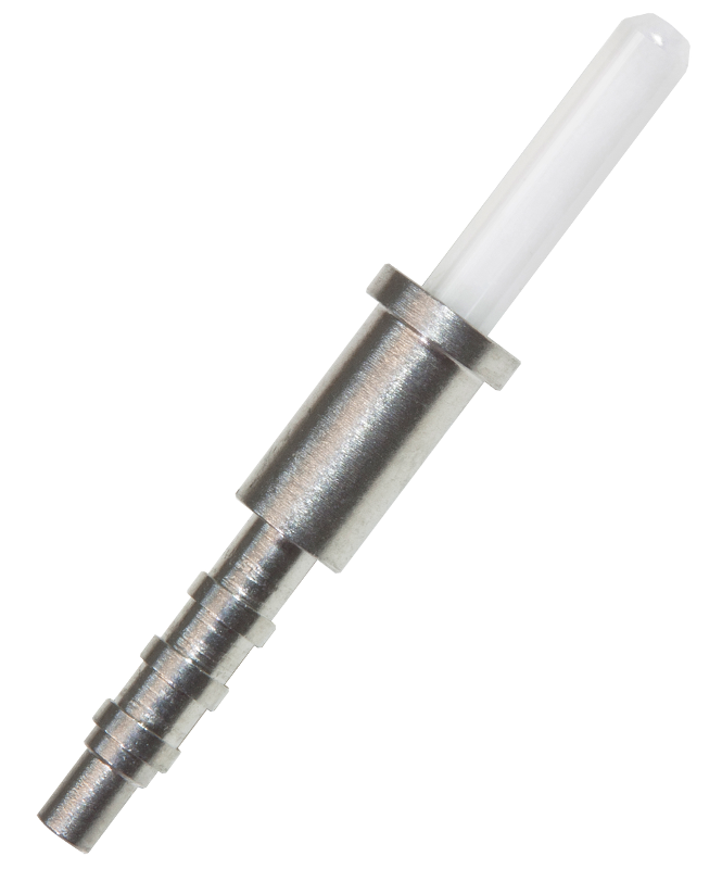
XiOptics M29504 slash 4 Style 1 pin terminus
XiOptics M29504/4 Style 1 pin terminus

The optical transition

How fiber moved into harsh environments

Optical fiber is now a familiar choice for moving large amounts of data through a secure, lightweight medium. Its use in demanding aerospace and defense systems, however, grew from decades of experimentation, standardization, and connector development.

1976

ALOFT Demonstrates the Potential

DARPA and the U.S. Air Force sponsored the Airborne Light Optical Fiber Technology program using an A-7 test aircraft. More than 300 copper cables were evaluated for replacement. A 40 kg, 1,260-meter, 302-cable harness was replaced by a 1.7 kg, 76-meter, 12-fiber cable that performed the required functions without identified flight-test drawbacks.

1980s–1990s

Military Adoption Expands

Fiber-optic data transmission appeared in programs including the B-1 bomber and MX missile. Studies estimated that replacing wire cabling in a B-1 could reduce aircraft weight by as much as 2,000 pounds, creating opportunities for greater payload, lower fuel use, and reduced operating cost.

Modern Systems

Fiber Becomes a Mainstay

Network-centric platforms including the F/A-18G, F-22, Eurofighter, and F-35 expanded the role of optical data links. Commercial aircraft such as the Boeing 777 and 787 and Airbus A380 also adopted fiber, while marine, armored-vehicle, missile, and field-communications applications continued to grow.

The mechanical link in an optical system

Why connectors and termini matter

Optical connectors and termini are among the most critical components in a fiber-optic data link. Along with the fiber itself, they are mechanical elements exposed to handling, contamination, mating wear, vibration, and potential physical damage.

Connectors make modular systems possible, but their geometry and stability directly affect insertion loss. System designers therefore need to understand not only network topology, but also the connector, terminus, cable, cleaning, and termination practices that preserve the optical path.

For many aerospace systems, the most widely used circular optical interconnects are based on the MIL-DTL-38999 Series III connector. Its triple-start ACME coupling thread, vibration-resistant ratcheting mechanism, environmental sealing, and broad range of shell materials make it a durable platform for mixed electrical, power, RF, and optical channels.

Aluminum, stainless-steel, and composite-shell versions provide different combinations of weight, corrosion resistance, EMI performance, and contact density. MIL-PRF-29504/4 and /5 termini allow standardized optical interfaces to operate within the familiar size 16 cavities of this connector family.

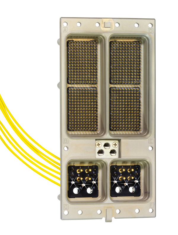
ARINC 600 connector assembly with electrical and optical sections
ARINC 600 assembly

From proprietary designs to open interfaces

The drive toward standardization

Early harsh-environment optical connector programs often relied on proprietary termini. Manufacturers commonly packaged optical interfaces around the envelope of a size 16 electrical contact, which made the products adaptable to many connector layouts but did not guarantee cross-mating or consistent performance.

As optical deployment accelerated in the early 1990s, military and industry stakeholders recognized the need for common interfaces. NAVAIR, NAVSEA, the Defense Supply Center Columbus, equipment manufacturers, and connector suppliers helped formalize optical connector requirements through working groups and open specifications.

Early MIL-T-29504 slash-sheet products included /1 and /2 front-release, rear-installed termini for MIL-C-28876 connector systems. Later work extended standardized termini across MIL-DTL-38999 and other military and aerospace platforms. The resulting MIL-PRF-29504 family established common optical-terminus interfaces while allowing multiple qualified sources.

ARINC 404 and ARINC 600 connector systems use M29504/6 pin and /7 socket termini where electrical, RF, power, and optical contacts share a gang insert. ARINC 801 later introduced a high-density optical interface based on 1.25 mm zirconia ceramic ferrule technology.

A connector built for electricity meets optics

The alignment challenge

MIL-DTL-38999 was originally designed as an electrical connector. When coupled, polarization keyways limit rotation between the plug and receptacle, but allowable mechanical tolerances can still affect cavity alignment as final coupling torque is applied.

Electrical contacts tolerate—and may even benefit from—mechanical contact pressure and slight displacement. Optical fibers do not. Misalignment between M29504/4 pin and /5 socket termini can offset the waveguide axes and raise insertion loss, particularly in larger-shell, multi-fiber configurations.

Connector and terminus suppliers have addressed this through stiffer shell materials, tighter polarization features, improved insert-cavity true position, more precise ferrules, and better-controlled alignment sleeves. These improvements support the continuing use of MIL-PRF-29504 interfaces across a wide range of connector packages.

Critical terminus design criteria

Four details that determine long-term optical stability

Qualified termini depend on a complete mechanical system. Each element must remain stable across vibration, shock, environmental exposure, handling, and repeated mating.

01

Resilient Spring Performance

The socket terminus spring must hold opposing glass faces together through vibration and shock while maintaining stable load and displacement over the connector’s mating life. Pre-setting, precision grinding, and a controlled outside diameter help prevent force variation and seal damage during installation or removal.

02

Protected Alignment Sleeves

Slotted alignment sleeves bring ferrules into precise axial and angular alignment. Stainless-steel sleeves are durable; zirconia ceramic sleeves provide superior hardness, surface finish, and dimensional stability. Ceramic designs should be protected from direct handling to reduce the risk of hidden damage.

03

Ferrule Geometry and Polish

Ferrule outside diameter, bore diameter, concentricity, and endface geometry all affect loss. Pre-radiused ceramic ferrules and controlled convex physical-contact polishing reduce air-gap reflections and support repeatable low-loss performance, particularly in single-mode systems.

04

Cable Strain Relief

The terminus must capture the cable without transferring load into the optical interface. Crimp sleeves, adhesive-lined heat shrink, and epoxy bonding have all been used. Modern Style 2 bonding cups support controlled adhesive application and capture the fiber, jacketing, and strength members in one cured assembly.

Continuing evolution

A common interface with improving precision

MIL-DTL-38999, ARINC, D-subminiature, and specialty connectors continue to evolve through new coupling methods, materials, mounting styles, and mixed-signal configurations. Within an optical channel, however, the terminus remains the primary mechanism for aligning two fibers.

Improvements in ceramic tolerances, spring control, protected alignment sleeves, endface preparation, and tuning have steadily increased the precision and repeatability of pin-and-socket termini. The objective remains the same: preserve a stable optical path while retaining the modularity, serviceability, and environmental performance of a rugged connector system.

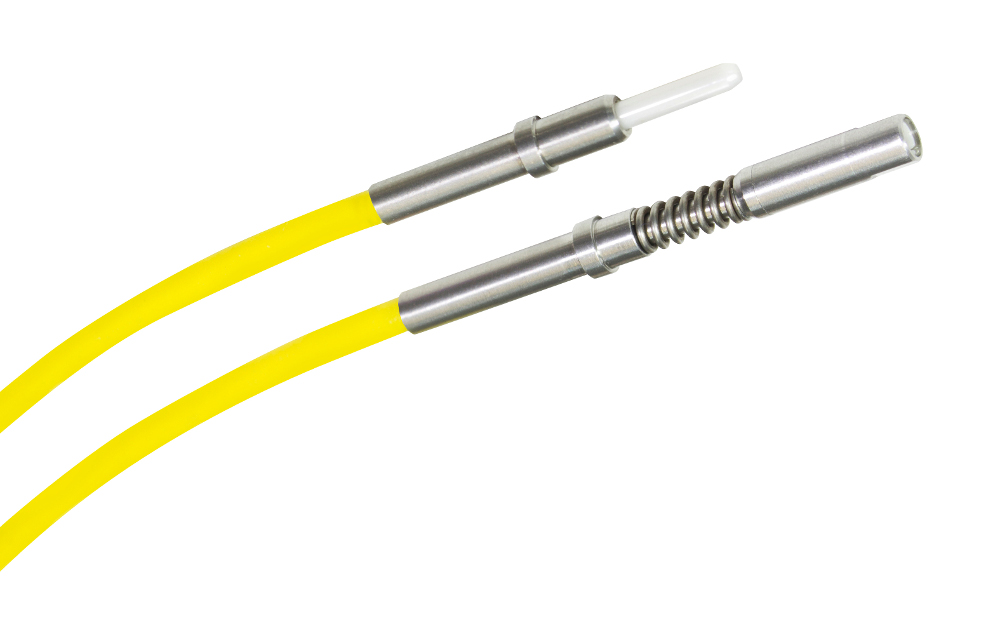
M29504/6 and /7 termini continue to support hybrid optical pathways in ARINC 404 and ARINC 600 gang inserts. Although these slash sheets are no longer active for new qualification activity, the interfaces remain relevant to programs that require established hybrid capability.

XiOptics Style 2 M29504 slash 6 pin and slash 7 socket termini on yellow fiber
XiOptics Style 2 M29504/6 pin and /7 socket termini

Continue exploring

Specifications and product information

Review the governing specification or return to the XiOptics MIL-PRF-29504 product family for configuration details.

Need help applying the M29504 interface?

Talk with XiOptics about connector geometry, fiber type, termination, and performance requirements.

Contact XiOptics