
Mil-PRF-29504 History
The use of optical fiber technology on the most advanced electronics systems is generally thought of being a rather common solution today for moving large amounts of data in across a secure and very lightweight medium. It wasn’t always this way however. Looking backward in time the optical revolution for harsh environment applications of optics began in 1976 with the U.S. Air Force. DARPA through the Air Force sponsored an experimental program called ALOFT (Airborne Light Optical Fiber Technology). In this program more than 300 copper based cables in an A-7 test bed aircraft were evaluated for suitability for replacement with optical cabling. At the end of the program the contractor had removed the 40 kg, 1260-meter long, 302-cable wiring harness substituting a 1.7 kg, 76-meter, 12-fiber cable. The cable proved to be able to performed all of the functions of the heavier cable. The aircraft during flight testing had improved performance and no drawbacks were seen. Through these experiments, ALOFT demonstrated that fiber optics could equal and exceed the performance of electrical wiring, especially in harsh environments. Into the 1980’s and early 1990’s both the B-1 bomber and the MX missile used fiber optics for data transmission. One study showed that, if all the wire cables in a B-1 could be replaced by fiber optics, the bomber’s weight would be reduced by up to 2,000 pounds. This could be used effectively to increase the amount of weaponry that can be carried, to save on fuel, and to generally decrease the cost of operating the aircraft. With the advent of the latest network centric programs such as F-18G, F-22, Eurofighter and F-35, fiber optics is now a mainstay in the advanced aerospace world. Its use has also spread into the commercial aircraft world, being found on Boeing 777, Boeing 787 and Airbus A380 platforms. The commercial aircraft companies have agressive goals of removing over 40 percent of their copper network cables and replace them with more reliable and lighter fiber optic solutions. Beyond the success of fiber optics in advanced avionics and communications systems its usage has grown to marine applications, heavy armor applications, tanker, missile and in Future Combat Systems architectures even individual troop-based communications. Along the way, its reliability has increased, costs have decreased an
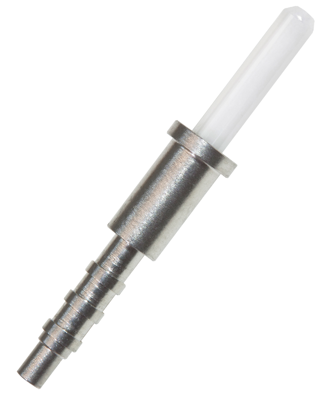
XiOptics 29504 / 4 “Style 1” Pin Terminus
d the full benefits of optical technology are being deployed to the benefit of the system’s performance envelopes.
Optical connectors and optical termini remain among the most critical elements in fiber optic data links as they and the actual fiber are the few mechanical elements that are subject to physical damage during use. Connectors are required for modularization of systems and their performance is key among all of the components in the optical link for establishing and maintaining reasonably stable optical links. Hence, it is critical for today’s systems designers to not only understand the network/link topology but also understand some of the critical elements of good connector/terminus/cable design.
In today’s aerospace systems the most widely used optical interconnect systems are based upon the Mil-DTL-38999 series III connector system. Given its wide use, excellent performance across a wide range of harsh environment MIL-DTL-38999 connectors have been continuously revised over the years to accommodate new coupling styles (series I, II and now the dominate Series III that incorporates a triple ACME thread coupling system with vibration resistant coupling mechanism and sealing), materials specifications (class designation) and configurations (mounting styles and cable interfaces).
Mil-C-38999 series III plug connectors carry most of the complexity within their assemblies. The plugs feature the ratcheting coupling nut, an EMI grounding spring and the basic plug body that couples with either a jamnut receptacle or flange mount receptacle connector. The connector series is sealed to maintain a water tight condition even when subjected to over 2m of submersion.
The connector series is available with aluminum, stainless steel and the latest products utilize composite plastic shells (carbon fiber loaded PEEK) with extremely dense signal pin packaging schemes that can accommodate power, electrical signal, optics and RF all in a single connector shell. With the Mil-T-29504 /4 and /5 optical terminus system delivering optical performance requirements per Mil-PRF-29504 this ageless connector continues to evolve to an even broader application base. But it is critical for end users to understand the strengths and weaknesses of the connector and terminus system so that proper use of the technology is applied.
In addition to Mil-DTL-38999 connector systems, harsh environment applications of optics are also found in Mil-C-23408 (D-subminiature), ARINC rectangular series (404 and 600) as well as a number of other specialty interconnects. Within these connector systems, unless an OEM desires to utilize a proprietary optical terminus solution, thus limiting component availability, the standard optical terminus solutions are based on open specifications managed by the Defense Supply Center Columbus (DSCC) Mil-PRF-29504 or specifications managed by the ARINC organization (ARINC801).
The original Mil-T-29504 optical termini systems were the leading technology roll-out platform for fiber optic connector solutions for harsh environments. Originally developed in the early 1990’s as it became apparent that transmission of data via optical media was a technology of the future. Several leading connector manufacturers initially developed unique solutions to package optics within the connector system but standardization prevented cross mating of these solutions. Typically, the manufacturers developed optical termini solutions around the common size #16 AWG electrical contacts. This allowed the optical termini to be installed into a wide range of readily available connector configurations but cross compatibility and significant performance variations were the norm. As time moved forward all of the connector companies realized that only series III Mil-DTL-38999 connectors could provide the protected environment necessary for successful optical systems if circular connectors were desired. 38999’s advanced features such as an advanced triple start ACME thread and complete cavity sealing to ensure a protective optical cavity during coupling are prime examples. The lack of compatibility quickly brought the attention of key decision makers within the military industrial complex. With the initial lead, the NavAir and NavSea organizations undertook efforts to develop and deploy specifications for optical interconnect solutions. The first of result these efforts was the MIL-C-28876 style circular connector system with a Mil-T-29504 style optical terminus. The first design used a front release, rear installation termini design and the optical terminus was defined by the first slash sheets of the Mil-T-29504 specification /1 and /2. With NavSea and NavAir backing the government through DSCC began a standards committee to define and formalize all of the militaries optical connector needs. Today, DSCC supports an on-going Fiber Optic Working Group that continues to define and refine optical connector systems for the entire military/industrial complex. Each of the major services, major equipment OEM’s and connector manufacturers are represented in that group and the standards that are being developed continue to evolve the basic Mil-C-28876 systems for Naval applications and Mil-DTL-38999 for airborne/ground applications. The optical termini for these connector systems are arrayed under the broad guidelines of Mil-PRF-29504 and Mil-T-29504.
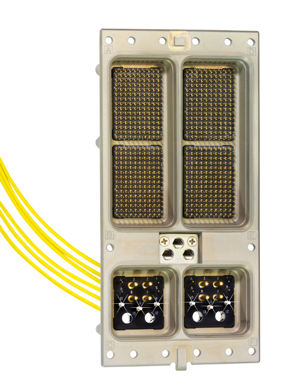
Arinc 600 Assembly
As optical fiber applications continued to grow through the 1990’s and into the early 2000’s the many major military programs deployed optical media into data backbones. During these roll-outs it was found that the general Mil-C-38999 connector system is as good a home as an optical package as any connector in the past, however since by its very design as an electrical connector many weaknesses in the overall package have been found. This is especially true in larger shell formats. When coupled, the Mil-C-38999 connector system relies on the polarization keyways to prevent rotation of the plug shell relative to the receptacle shell. In order to maintain interminability of the connectors from manufacturer to manufacturer, tolerances within the keyways is maintained by specification but values can be fairly loose. This enables a condition where-in cavity alignment is jeopardized during application of final coupling torque. For electrical contact, this historically has not been an issue as pressing copper based pins, harder onto copper based pins actually ensures more stable pin-to-socket resistance levels. Mil-T-29504 /4(pin) and /5(socket) in size 16 cavities the potential for cavity mis-alignment can lead to axial misalignment of the mated pin/socket solution. This can lead to significantly higher optical insertion losses than expected as the primary axis of the waveguide within the optical fiber would likewise be misaligned. Even with larger core multi-mode fiber it is not uncommon to see insertion losses in excess of 0.5 db when multi-fiber connector configurations are selected. There are activities underway to improve this, from utilizing stainless steel as a manufacturing media for the connectors to just tightening up polarization keyways and insert cavity true positions. All of this portends a long future for Mil-T-29504 optical solutions in a variety of package solutions.
Working groups that continue to study the connector and terminus system have called for termini insert density equal to or better than the current MIL-C-38999 Series III, as well as compliance with MIL-T-29504/4 and /5 rear release and rear insertable specifications.
Mil-T-29504 also blankets the development of other standard optical termini solutions. For ARINC 404 and 600 series connectors the only optical terminus system available that allows for hybrid electro/optical insert gangs are the /6 and /7 termini. These specifications have been removed from active services but suppliers still deliver the terminus system to meet demands from OEM’s who need this hybrid capability. More recently, the ARINC organization, lead by requirements from the Boeing Commercial Aircraft Co. have release the 801 specification. This specification defines a new optical terminus system using the latest 1.25mm zirconia ceramic ferrule technology and offers high density, high performance all optical gangs for ARINC connector systems.
In the development of optical termini connector engineers must follow some very stringent criteria. Likewise, optical systems engineers must be sure the suppliers of the product have followed these criteria to ensure stable, life-long performance of their products. The following design features of qualified termini are considered critical if target insertion loss levels are to be achieved:
- A resilient spring characteristic to secure ferrules within the socket. The spring must provide a sufficient load bias to hold the two termini glass faces together through all environmental tests such as vibration and shock. The load/displacement characteristics of the spring element must be stable across environments and across the mating life of the connector system. Some manufacturers skip the costly step of pre-setting the springs and also grinding/closing the springs used in optical termini. This is one of the questions that should be asked and verified as a termini supplier is selected. Quality within the product will show up in even the smallest components. The terminus spring is found on the socket half of the terminus only. If properly designed the spring has an outer diameter sufficiently below the terminus’ largest diameter that it will not catch nor damage cavity seals during installation or removal. The image below shows a typical spring installation.
- The alignment sleeves provide the mechanical means necessary for bringing the two terminus ferrules in precise axial and angular alignment. The sleeves are slotted to offer a resilient encasement of the terminus ferrule. Sleeve material selection is critical in the terminus design. The two most widely used materials are stainless steel and zirconia ceramic. Stainless steel sleeves work well and are extremely durable; however, they do not offer the surface finish quality, hardness, or dimensional stability of ceramics. When mated with hard ceramic ferrules, the softer stainless alignment sleeves can exhibit wear characteristics which may result in unwanted contamination. Ceramic sleeves can be manufactured to tightly controlled tolerances but are more fragile than stainless. This design concern has been over-come with the use of metallic protective alignment sleeve covers. As systems have been rolled out over the past decade the general feelings in the market are that ceramic alignment sleeves are preferred but the designs should be such that handling of the alignment sleeves is not possible by users. This prevents uses from inducing unseen cracks into the ceramics by stressing them during handling. Many Mil-T-29504 optical termini designs on the market utilize a loose sleeve design where-in the sleeve is covered with a simple hood. If the hood is removed the alignment sleeve can be directly accessed. These designs should be avoided if possible unless stainless steel alignment sleeves are selected. Only designs where-in the sleeve is contained and removed as an integral part of the hood should be selected for use in fielded applications where technicians may not have sufficient training to ensure proper sleeve handling.
-
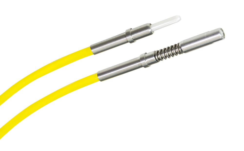
XiOptics “Style 2” 29504 / 6 Pin and 29504 / 7 Socket Termini
Ferrule designs must conform to two critical dimensional features: the outer and inner diameter of the ferrule and the concentricity of these two diameters. The end-face profile of the terminus ferrule must also be configured or polished to eliminate unwanted back reflections in single mode fibers. This can be achieved in two ways: by polishing the fiber end-face and ferrule on a rubber pad, or by using pre-radiused ceramic ferrules. Such convex polishing techniques reduce fresnel air-gap reflections to achieve loss values as low as .2dB for multimode fiber. Physical Contact (PC) and concave polishing methods are both considered acceptable, depending on the application and ability to clean the terminus after each insertion. However, PC polish must be used to achieve the .3dB design goal. In the latest revisions of the Mil-T-29504 pre-radius ferrules are desired and system designers should select termini designs that only provide that option. This ensures that cable manufacturers will have a more stable process during the manufacture of designed cables.
- Termini must be able to provide a mechanism to provide strain relief to the fiber optic cable for captivation. Three methods are considered suitable: crimp sleeve, shrink sleeve, and epoxy. Epoxy is the latest and generally accepted as the preferred method. Crimp sleeve designs introduce the potential for mechanical damage of the terminus or optical fiber during the crimping operation. Likewise, it is often difficult to inspect crimp quality especially on non-strength member fiber. Shrink sleeve has long been as the standard for Mil-T-29504 optical termini but application of the sleeving and proper termination is highly operator dependent. In addition the internal adhesive can be messy and easily overheated. The latest terminus designs conform to the Type 2 requirements of Mil-T-29504 for /4 and /5 termini. Type 2 utilize an integrated bonding cup as a part of the rear of their terminus. The bonding cup allows operators to directly apply fiber bonding agents such as EpoTek 353ND into the ferrule as well as the rear of the terminus. Once applied the entire fiber/cable is plugged into the terminus and the adhesive cured in a single controlled operation. The optical fiber and all of its jacketing/support is now directly bonded into the terminus for a truly high performance and sealed solution. A rear view of XiOptics Type 2 terminus pair illustrates the bonding cup solution.
Given their wide use, excellent performance across a wide range of harsh environment MIL-DTL-38999, ARINC and D-Subminiature connectors have been continuously revised over the years to accommodate new coupling styles, materials specifications and configurations. The connector series are available with aluminum; stainless steel and now the latest products utilize composite plastic shells with extremely dense signal pin packaging schemes that can accommodate power, electrical signal, optics and RF all in a single connector shell. If optical channels are desired within the connector system the fiber optic contact or terminus is the primary alignment mechanism for connecting two optic fibers. Over the past two decades there have been dramatic tolerance improvements in terminus design to insure precise, repeatable, axial and angular alignment between pin and socket termini within connector shells. Connector suppliers who remain on the cutting edge of development demonstrate this by delivering continuously improved ceramic components, ever evolving features such as tuning and a growing porfolio of products based around common termini platforms.
To view technical details on the Mil-PRF-29504 specification, view the Mil-PRF-29504 specification document by clicking here.
Individual Mil-PRF-29504 termini have their own specification documents. View them by visiting our individual Mil-PRF-29504 product pages.